2026-04-10
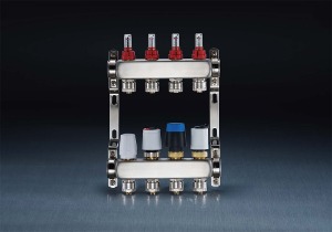
Hydronic radiant floor heating distribution: The 3/4-Inch HVAC Stainless Steel Manifold connects a single supply line from a boiler or heat pump to 4–12 individual floor loops (each typically 1/2 inch PEX tubing). Stainless steel resists corrosion from oxygen diffusion in water systems, extending service life beyond 20 years.
Chilled water fan coil units: In commercial buildings, a 3/4-inch stainless manifold serves as the central distribution point for chilled water to multiple fan coil units (FCUs). The material withstands low temperatures (down to -10°C) without embrittlement, unlike brass which may crack under thermal cycling.
Dual-temperature changeover systems: The manifold can supply either heated or chilled water from the same distribution network. Stainless steel maintains dimensional stability across temperature swings from 5°C to 85°C, with thermal expansion coefficient of 17 μm/mK (compared to 19 μm/mK for copper and 22 μm/mK for brass).
Advantages over alternative materials:
Integration with primary and secondary loops
In hydronic HVAC systems, the 3/4-inch stainless steel manifold acts as the interface between the primary circulation loop (boiler or chiller) and secondary distribution circuits. The primary loop delivers fluid at a set temperature (typically 45–65°C for heating, 5–12°C for cooling). The manifold splits this flow into multiple secondary circuits, each serving a zone or terminal device (radiant floor mat, fan coil, radiator). A closely spaced tee arrangement (distance between supply and return manifold connections below 300 mm) ensures hydraulic separation, meaning pressure fluctuations in secondary circuits do not affect primary pump operation.
Pressure and temperature regulation points
The manifold central body includes provisions for system monitoring and control. A pressure gauge port (1/4 inch NPT) accepts a gauge reading 0–10 bar or 0–150 psi. A temperature sensor well (typically 150 mm deep, 6 mm diameter) holds an immersion sensor for building management system (BMS) integration. An automatic air vent (3/8 inch connection) removes trapped air from the highest point of the manifold, preventing flow reduction and noise. For systems with variable speed pumps, a differential pressure sensor across the supply and return manifolds provides feedback for pump speed control, maintaining a set pressure difference of 10–50 kPa.
Compatibility with piping materials
The 3/4-inch stainless manifold connects to various pipe types using appropriate adapters. For copper pipe, a stainless-to-copper threaded adapter (with dielectric washer) prevents galvanic corrosion. For PEX tubing, a stainless steel barbed insert with compression ring creates a sealed connection. For steel pipe (black or galvanized), direct threaded connections (NPT or BSPT) are used, with PTFE tape or pipe dope sealing the threads. The manifold’s stainless steel body does not require dielectric unions when connected to other stainless components, but does require them when connecting to copper, brass, or carbon steel to prevent bimetallic corrosion.
System expansion and modification
The modular design of the 3/4-inch manifold allows future system changes. Additional branch ports (blanked with 3/4-inch caps) can be opened by removing the cap and installing a new outlet valve. For systems requiring more than the original number of circuits, multiple manifolds can be connected in series using a 3/4-inch nipple between manifold bodies. The supply and return manifolds are mounted on mounting rails (typically 25 mm × 10 mm steel channels) with 150–200 mm vertical separation. This rail system allows sliding manifolds laterally to align with new branch pipe positions when retrofitting additional zones.
A. Material grade selection and corrosion resistance
304 stainless steel (ASTM A269): Suitable for closed-loop HVAC systems with treated water (pH 7–9, chloride below 200 ppm). Maximum chloride concentration for 304 is 200 ppm at 20°C, decreasing to 50 ppm at 60°C. Do not use for seawater or de-icing fluid systems.
316 stainless steel (ASTM A312): Required for open-loop systems (e.g., ground source with direct well water) or where chlorides exceed 200 ppm. Molybdenum content (2–3%) provides pitting resistance equivalent to 304 at double the chloride concentration. Specify 316 for coastal installations within 3 km of salt water.
Surface finish: Internally, a 180-grit or finer finish (Ra ≤ 0.8 μm) reduces deposit accumulation and biofilm growth. Externally, a mill finish (Ra 2–4 μm) is acceptable for indoor installations, but a brushed or electropolished finish (Ra ≤ 0.4 μm) is specified for clean rooms or food processing HVAC.
B. Pressure and temperature ratings
Maximum working pressure (MWP) at 20°C: 25 bar (362 psi) for 304 and 316 with 1.5 mm wall thickness, based on ASME B31.9 (building services piping). Reduce pressure by 0.5% per 1°C increase above 50°C (e.g., at 90°C, MWP = 25 bar × [1 – 0.005×(90-50)] = 20 bar).
Burst pressure: Typically 4× MWP (100 bar) at 20°C. Hydrostatic testing after manufacture is conducted at 1.5× MWP (37.5 bar) for 10 minutes with no leakage or permanent deformation.
Operating temperature range (continuous): -20°C to 150°C for 304 and 316 (limited by gasket materials, not metal). For systems with steam (above 120°C), specify graphite or metal gaskets instead of EPDM or NBR.
C. Branch configuration and flow distribution
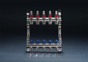
Number of branch ports: Typically 4, 6, 8, 10, or 12 ports per manifold. Port spacing: 50–80 mm center-to-center for 3/4-inch branches, allowing space for valve handles and flow meters.
Supply and return manifold orientation: Install with branch ports pointing downward (for floor heating) or horizontally (for wall-mounted fan coils). Avoid upward-pointing branches in water systems, as trapped air accumulates in valve bodies.
Flow balancing method: Options include (1) integral venturi flow meters with regulating stems (accuracy ±5% of reading), (2) manual ball valves with memory stops (cost lower but no flow indication), or (3) thermal actuator valves (for electronic zone control). Specify venturi type for systems requiring balancing verification without external tools.
Copyright © Zhejiang Jiafu HVAC Co., Ltd. All Rights Reserved.

 English
 русский