2026-05-22
Fluid distribution and collection in industrial systems.
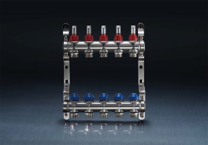
A stainless steel manifold is a component that distributes fluid from a single inlet to multiple outlets or collects fluid from multiple inlets to a single outlet. Common configurations include 2 to 20 ports, with port sizes ranging from 1/8 inch NPT to 4 inch flanged connections. Stainless steel (typically 304, 316, or duplex grades) is selected when the fluid is corrosive (chemicals, seawater, acidic solutions), high-purity (pharmaceuticals, semiconductors), or high-temperature (steam, hot oils above 200°C). For a chemical dosing skid with 8 injection points, a 316L stainless steel manifold with 1/2 inch ports distributes 20–50 L/min of 10% sulfuric acid at 0.5–1.0 MPa. The manifold body is machined from solid bar or fabricated from welded pipe; machined bar manifolds (forged or rolled) have no internal weld seams, reducing leak paths and corrosion initiation sites. Typical wall thickness for 316L bar-stock manifolds at 1.0 MPa working pressure is 3–5 mm for 1/2 inch ports, providing a safety factor of 5–8×.
Material selection based on service environment.
The choice of stainless steel grade affects corrosion resistance and cost. For general water and mild chemicals (pH 5–9, chloride below 200 ppm), 304 stainless steel (18% Cr, 8% Ni) is sufficient. For coastal environments or fluids with 200–1,000 ppm chloride, 316 stainless steel (16% Cr, 10% Ni, 2% Mo) resists pitting corrosion better; the molybdenum content stabilizes the passive layer. In seawater or high-chloride applications (1,000–20,000 ppm), duplex stainless steel (2205, 25% Cr, 5% Ni, 3% Mo) or super duplex (2507) is specified. A 316 manifold in seawater at 25°C shows pitting (0.1–0.3 mm depth) after 1–2 years; a 2205 duplex manifold shows no pitting after 5–10 years. For high-purity applications (ultrapure water, semiconductor chemicals), the manifold interior must be electropolished to achieve surface roughness below 0.25 µm Ra, reducing particle entrapment and bacterial adhesion. Electropolished 316L manifolds for pharmaceutical water-for-injection (WFI) systems are cleaned to verify endotoxin levels below 0.25 EU/mL and conductivity below 1.3 µS/cm at 25°C.
Port configuration and flow balancing.
Manifold port arrangement affects flow distribution uniformity. Linear manifolds (ports in a straight line) have higher flow to the first port and lower to the last port unless designed with progressively smaller port diameters or internal flow restrictors. For a 10-port linear manifold with identical ports and a constant pressure supply, flow variation from first to last port can be 20–40%. For applications requiring equal flow (e.g., parallel heat exchangers, spray nozzles), designers use reverse-return manifolds (supply and return headers on opposite sides) or install balancing valves on each port. Radial manifolds (ports arranged radially around a central hub) provide more uniform distribution; flow variation between radial ports is typically 5–15%. The internal flow area should be at least 2× the sum of port areas to minimize pressure drop. For a manifold with 8 ports of 10 mm² area each, total port area is 80 mm²; the manifold bore should be at least sqrt(80 × 2 × 4 / π) = sqrt(203) = 14 mm diameter.
End connections and installation practices.
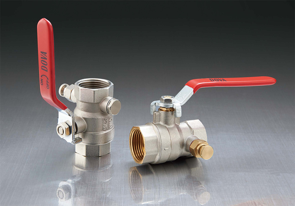
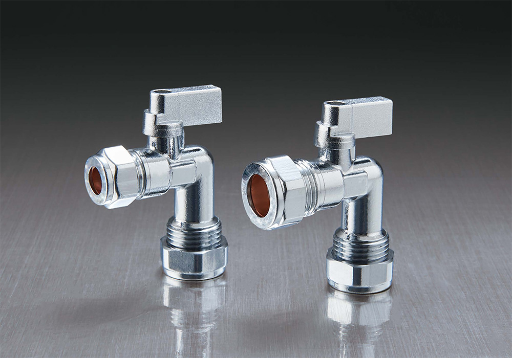
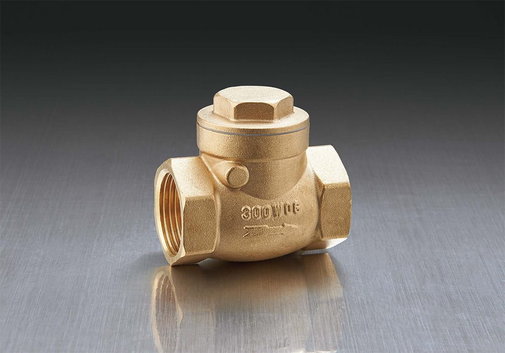
Stainless steel manifolds connect to piping via threaded (NPT, BSPT), flanged (ANSI/ASME B16.5), or welded (butt weld or socket weld) ends. Threaded connections are common for manifolds up to 1 inch; PTFE tape (3–5 wraps) or anaerobic thread sealant prevents galling (cold welding) between stainless steel threads. Galling occurs when pressure and friction cause localized welding of threads; for 316 stainless steel, galling begins at assembly torque of 40–50 Nm for 1/2 inch NPT connections. Using anti-seize compound (nickel or copper-based) reduces galling risk. For flammable or toxic fluids, welded connections are preferred because they eliminate potential leak paths. Automatic orbital welding of manifold stub ends to tubing produces welds with penetration depth 1.0–1.5 mm, visual inspection acceptance per ASME B31.3, and radiographic testing for critical systems. A welded manifold for a hydrogen fuel cell test stand (pressure 35 MPa) requires 100% X-ray inspection of all welds.
European standards: EN 1092, PED, and material traceability.
European stainless steel manifolds must comply with the Pressure Equipment Directive (PED) 2014/68/EU for systems operating above 0.5 bar gauge pressure. Manifolds are classified into risk categories I, II, III, or IV based on fluid group (hazardous or non-hazardous) and pressure-volume product. For a water manifold (non-hazardous fluid) at 1.0 MPa with 1 liter internal volume, the pressure-volume product is 1.0 MPa × 1.0 L = 1.0 MPa·L, falling into Category I (low risk). Category I requires manufacturer declaration of conformity (DoC) with technical documentation. For a chemical manifold (hazardous fluid, Group 1) at 10 MPa with 0.5 L volume, the product is 5.0 MPa·L, requiring Category III or IV, which involves Notified Body inspection and quality system approval. Flange dimensions follow EN 1092-1: for PN (nominal pressure) 10, 16, 25, 40, 63, 100, 160, 250, 320, 400. PN 40 (4.0 MPa rating at 20°C) is the most common for industrial manifolds. Material certification per EN 10204: Type 3.1 (mill certificate with chemical analysis and mechanical test results) is standard; Type 3.2 (third-party inspection) is required for Category IV manifolds. European practice mandates full material traceability from melt to finished manifold. Each manifold receives a unique serial number linked to the original mill certificate. A 316L manifold for a dairy processing line (PED Category II) retains traceability records for 10 years after the last production batch. Surface finish for hygienic applications (food, beverage, pharmaceutical) is specified by EHEDG guidelines; internal roughness must be below 0.8 µm Ra for easy cleaning and below 0.4 µm Ra for CIP (clean-in-place) systems.
Copyright © Zhejiang Jiafu HVAC Co., Ltd. All Rights Reserved.

 English
 русский